48V LiFePO4 Battery Management Systems (BMS): Active vs. Passive Balancing & Thermal Safety
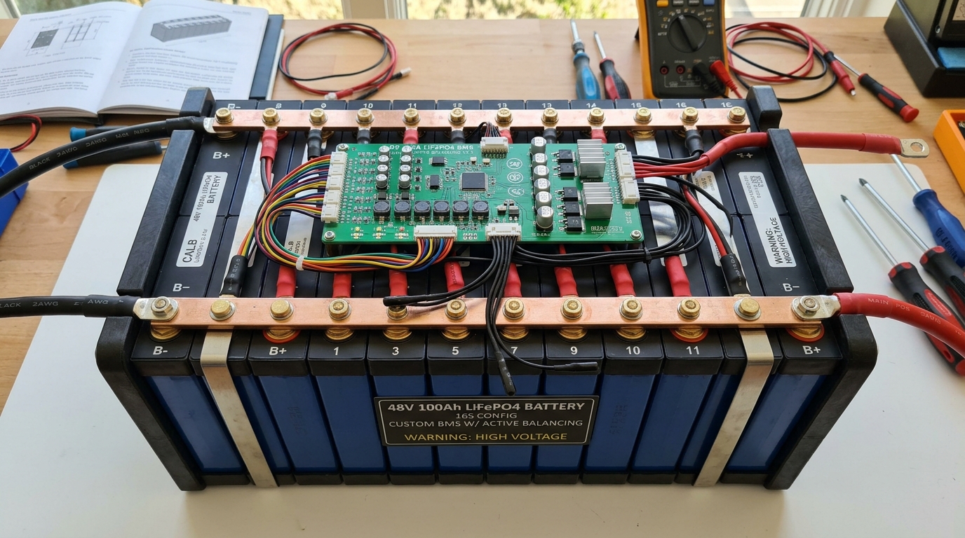
Table of Contents
“Designing an industrial 48V (16S) LiFePO4 Battery Management System (BMS) requires balancing high current delivery with cell-level protection. Small capacity imbalances between cells compound over hundreds of charge cycles, reducing total usable battery capacity and accelerating degradation. This guide reviews active capacitive balancing, multi-channel NTC temperature monitoring, and low-inductance solid-state switching.”
1. Active Capacitive Balancing vs. Passive Resistive Dissipation
Passive balancing bleeds off excess charge from high-voltage cells as heat through power resistors, wasting energy and generating up to 15W of localized heat. Active balancing transfers charge from higher-voltage cells to lower-voltage cells using inductive or switched-capacitor converter circuits, operating at up to 92% transfer efficiency with balancing currents up to 2A.
Key Engineering Takeaways
- Passive Balancing: Simple, low cost, but dissipates excess cell energy as heat (limited to 50–100mA)
- Active Switched-Capacitor: High efficiency (~90%), fast balancing (1A–2A), minimal heat generation
- Extends overall 16S battery pack cycle life by up to 30%
2. Multi-Channel NTC Thermal Monitoring & Hotspot Prevention
Lithium iron phosphate cells require tight thermal boundaries (0°C to 45°C during charging; -20°C to 60°C during discharge). We place 10kΩ NTC thermistors directly on cell inter-connect busbars and internal power MOSFET heat sinks, sampled by a dedicated AFE IC with sub-1°C precision.
// 16S BMS Protection Threshold Configuration
Cell Over-Voltage (COV):    3.65 V  (Delay: 1000 ms)
Cell Under-Voltage (CUV):   2.50 V  (Delay: 1000 ms)
Charge Over-Current (OCC):  100 A   (Delay: 500 ms)
Discharge Over-Current (OCD): 200 A (Delay: 100 ms)
Short Circuit Protection:   500 A   (Delay: 200 μs)
3. High-Side Solid-State MOSFET Protection vs. Mechanical Contactors
Solid-state high-side N-channel MOSFET switches offer sub-millisecond response times to short circuits without the arc degradation or mechanical bounce of heavy electromagnetic contactors. Using back-to-back low RDS(on) MOSFETs (e.g., 0.5 mΩ per FET) minimizes static conduction losses at 100A continuous load.
Summary & Engineering Verdict
Combining active capacitive balancing with solid-state protection switches and multi-point thermistor sensing creates a long-lasting, ultra-reliable 48V LiFePO4 battery management system.
Frequently Asked Questions
Why is active balancing preferred for large 48V LiFePO4 battery packs?
Active balancing moves charge directly between cells rather than wasting it as heat. This allows high balancing currents (1A–2A) without heating up the enclosure, keeping high-capacity packs balanced quickly.
How fast must a BMS trigger short-circuit protection?
A solid-state BMS must detect and disconnect a dead short circuit within 100 to 300 microseconds to prevent irreversible thermal damage to battery cells and copper traces.
Custom Battery Management & Power Conversion Design
Need a custom BMS for 12V to 800V energy storage or electric mobility? CircuitBEES engineers high-reliability power systems.

CircuitBEES Engineering Team
Verified Engineering TeamThe CircuitBEES engineering group brings together senior PCB layout artists, mechatronics designers, and embedded systems developers. By publishing our hands-on findings from high-speed memory tuning to deep mechatronic systems—such as our landmark countertop appliance, India's first fully automatic roti maker—we aim to raise the standard for hardware documentation.
Share this guide with your team
Help other hardware and embedded engineers optimize their designs.