Industrial BMS Architecture: Active Cell Balancing, Safe Operating Area & High-Side Disconnect

Table of Contents
“Designing safe, high-capacity Lithium-Ion and LiFePO4 battery packs for industrial robotics, electric vehicles, and grid storage requires an uncompromising Battery Management System (BMS). A reliable BMS must continually monitor individual cell voltages to millivolt accuracy, track State of Charge (SoC) and State of Health (SoH), and disconnect current flow in microseconds during over-current or thermal runaway events.”
1. Precision Analog Front-End (AFE) Architecture
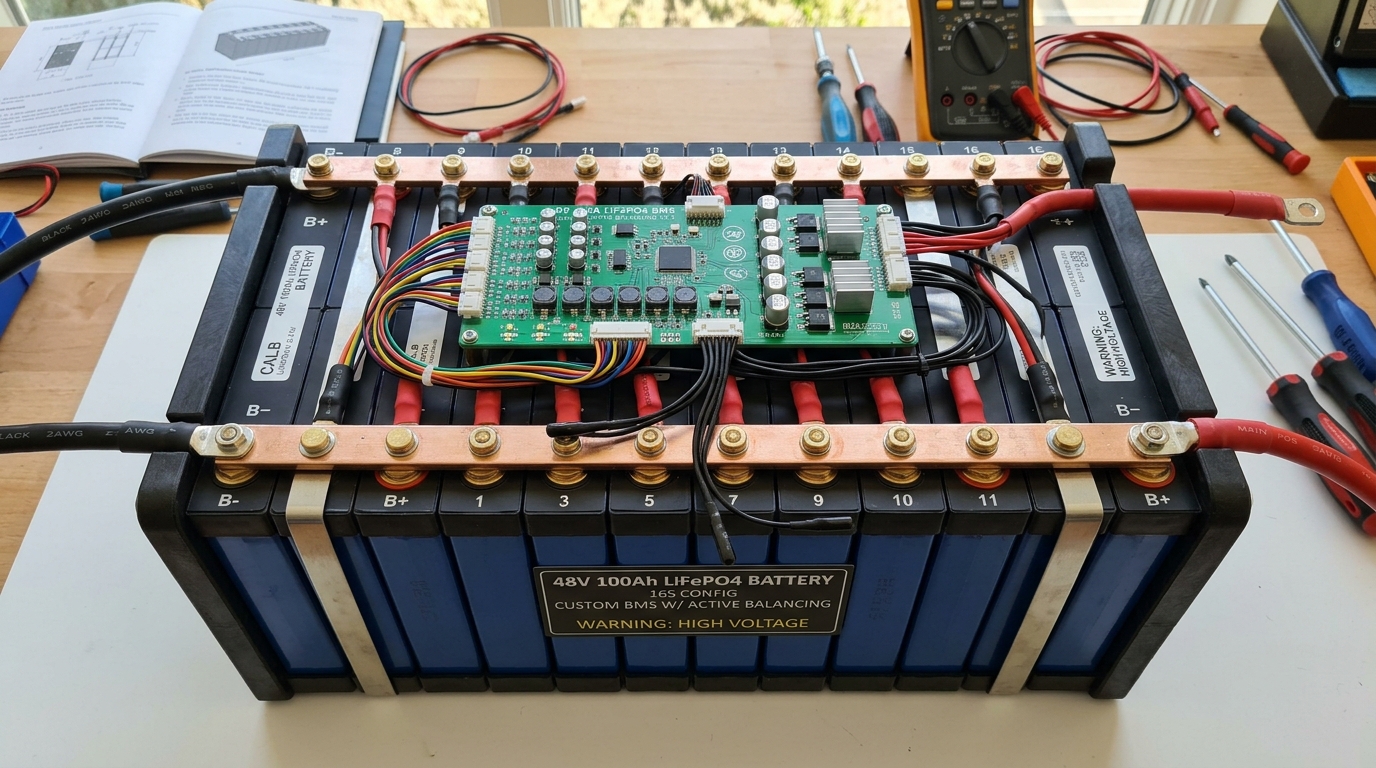
Dedicated multi-cell AFE ICs (such as Texas Instruments BQ76952 or Analog Devices ADBMS1818) sample cell voltages across series stacks up to 16S or higher. Differential low-pass RC filters at each cell input filter PWM inverter switching noise, while synchronous Coulomb counting with a low-drift shunt resistor (e.g., 0.5 mΩ, 15 ppm/°C) calculates instantaneous pack current.
Key Engineering Takeaways
- Maintain voltage sampling precision within ±1.5 mV across -40°C to +85°C
- Place NTC thermistors across the pack, allocating at least one probe per 4 adjacent cells
- Implement hardware-level primary overvoltage/undervoltage comparator interrupts independent of MCU firmware
2. Active vs. Passive Cell Balancing
Passive balancing bleeds excess charge from top cells through shunt resistors as heat (typically 50–200 mA). For high-capacity packs (>50 Ah), active balancing uses capacitive or inductive charge-shuttling to transfer energy from high cells to lower cells with 90%+ efficiency, preventing localized hot-spots.
// Dual-Tier High-Side MOSFET Disconnect Circuitry
* Charge Cutoff: High-Side Back-to-Back N-Channel MOSFETs with charge pump
* Short-Circuit Protection Trip Time: < 15 microseconds (Hardware Comparator)
* Pre-Charge Resistor Relay: Limits inrush current into capacitive inverter loads
* Galvanic Isolation: Digital isolators (5 kVrms) between AFE and host CAN/RS-485 bus
3. Functional Safety & Redundant Protection Interlocks
Compliance with ISO 26262 (ASIL-C/D) and UL 2271 mandates secondary hardware protection. If the primary MCU fails or hangs, a dedicated secondary safety monitor triggers a chemical fuse (e.g. self-control protector) to permanently blow the power path before lithium plating or thermal propagation occurs.
Summary & Engineering Verdict
Engineering a world-class BMS requires millivolt-level measurement precision, intelligent thermal telemetry, and multi-tier failsafe disconnects to deliver long cycle life and absolute pack safety.
Frequently Asked Questions
Why is high-side switching preferred over low-side switching in industrial BMS?
High-side switching maintains a continuous ground reference for the entire system, preventing ground-shift communication errors across CAN/UART buses and avoiding dangerous floating-ground faults.
What is the difference between SoC and SoH in battery management?
State of Charge (SoC) represents the immediate remaining usable capacity (0–100%), whereas State of Health (SoH) measures permanent capacity degradation and internal resistance increase over the battery's total lifecycle.
Custom Battery Management & Power System Design
From lightweight wearable Li-Po systems to 48V/400V industrial motive packs, CircuitBEES architects certified BMS hardware.

CircuitBEES Engineering Team
Verified Engineering TeamThe CircuitBEES engineering group brings together senior PCB layout artists, mechatronics designers, and embedded systems developers. By publishing our hands-on findings from high-speed memory tuning to deep mechatronic systems—such as our landmark countertop appliance, India's first fully automatic roti maker—we aim to raise the standard for hardware documentation.
Share this guide with your team
Help other hardware and embedded engineers optimize their designs.