Field Oriented Control (FOC): Sensorless Brushless DC Motor Drive Architecture
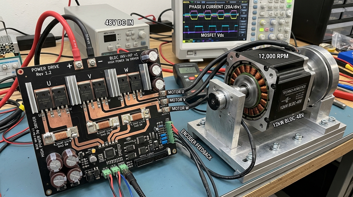
Table of Contents
“Field Oriented Control (FOC), or vector control, transforms complex three-phase AC motor currents into two decoupled DC components: direct current (Id, controlling flux) and quadrature current (Iq, controlling torque). This enables smooth, high-efficiency motor operation from zero speed to maximum RPM with maximum torque per ampere.”
1. Mathematical Foundations: Clarke & Park Transforms
The Clarke transform converts three-phase stator currents (Ia, Ib, Ic) into a stationary two-axis reference frame (Iα, Iβ). The Park transform then rotates these coordinates into a rotating reference frame aligned with the rotor magnetic flux (Id, Iq).
Key Engineering Takeaways
- Clarke Transform: 3-phase (a, b, c) -> 2-phase stationary (α, β)
- Park Transform: Stationary (α, β) -> Rotating (d, q) aligned with rotor
- Set Id = 0 for maximum torque efficiency in surface-mount permanent magnet motors
2. Space Vector PWM (SVPWM) & Switching Dead-Time
Space Vector PWM (SVPWM) synthesizes sinusoidal phase voltages with 15% higher DC bus voltage utilization compared to standard sinusoidal PWM. Inserting precise dead-time (e.g., 200ns to 500ns) between top and bottom MOSFET switches prevents catastrophic shoot-through short circuits.
// 20 kHz FOC Current Loop Execution Timing
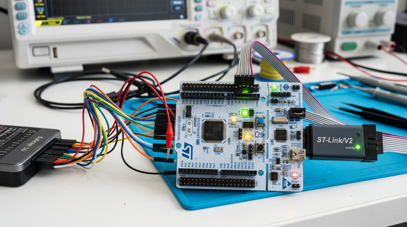
1. Trigger 3-phase ADC current sampling at center of PWM cycle (zero switching noise).
2. Execute Clarke & Park Transforms (< 2 μs on Cortex-M4 DSP instructions).
3. Run dual PI controllers for Id and Iq currents.
4. Execute Inverse Park & SVPWM generation (< 1.5 μs).
Total Execution Time: < 5 μs (leaves 45 μs for speed/position loops)
3. Inline vs. Low-Side Shunt Current Measurement
Inline current sensors sample phase current continuously throughout the PWM cycle, but require high common-mode rejection amplifiers. Low-side shunt sensing uses inexpensive low-side resistors, but requires precise ADC trigger timing during the bottom PWM switch conduction period.
Summary & Engineering Verdict
Implementing FOC with Space Vector PWM delivers smooth, quiet, and ultra-efficient torque control for robotics, electric mobility, and automated appliances.
Frequently Asked Questions
Why is FOC superior to trapezoidal 6-step commutation?
FOC drives motor coils with smooth sinusoidal currents, eliminating torque ripple, acoustic noise, and vibration while delivering higher efficiency across all speed ranges.
Why must ADC current sampling occur at the center of the PWM cycle?
Sampling at the center of the PWM cycle occurs when switching transients have settled, providing clean average current readings with zero switching noise.
Motor Control & Embedded Robotics Firmware
CircuitBEES develops custom FOC algorithms, high-voltage BLDC inverter hardware, and precision servo drive electronics.

CircuitBEES Engineering Team
Verified Engineering TeamThe CircuitBEES engineering group brings together senior PCB layout artists, mechatronics designers, and embedded systems developers. By publishing our hands-on findings from high-speed memory tuning to deep mechatronic systems—such as our landmark countertop appliance, India's first fully automatic roti maker—we aim to raise the standard for hardware documentation.
Share this guide with your team
Help other hardware and embedded engineers optimize their designs.